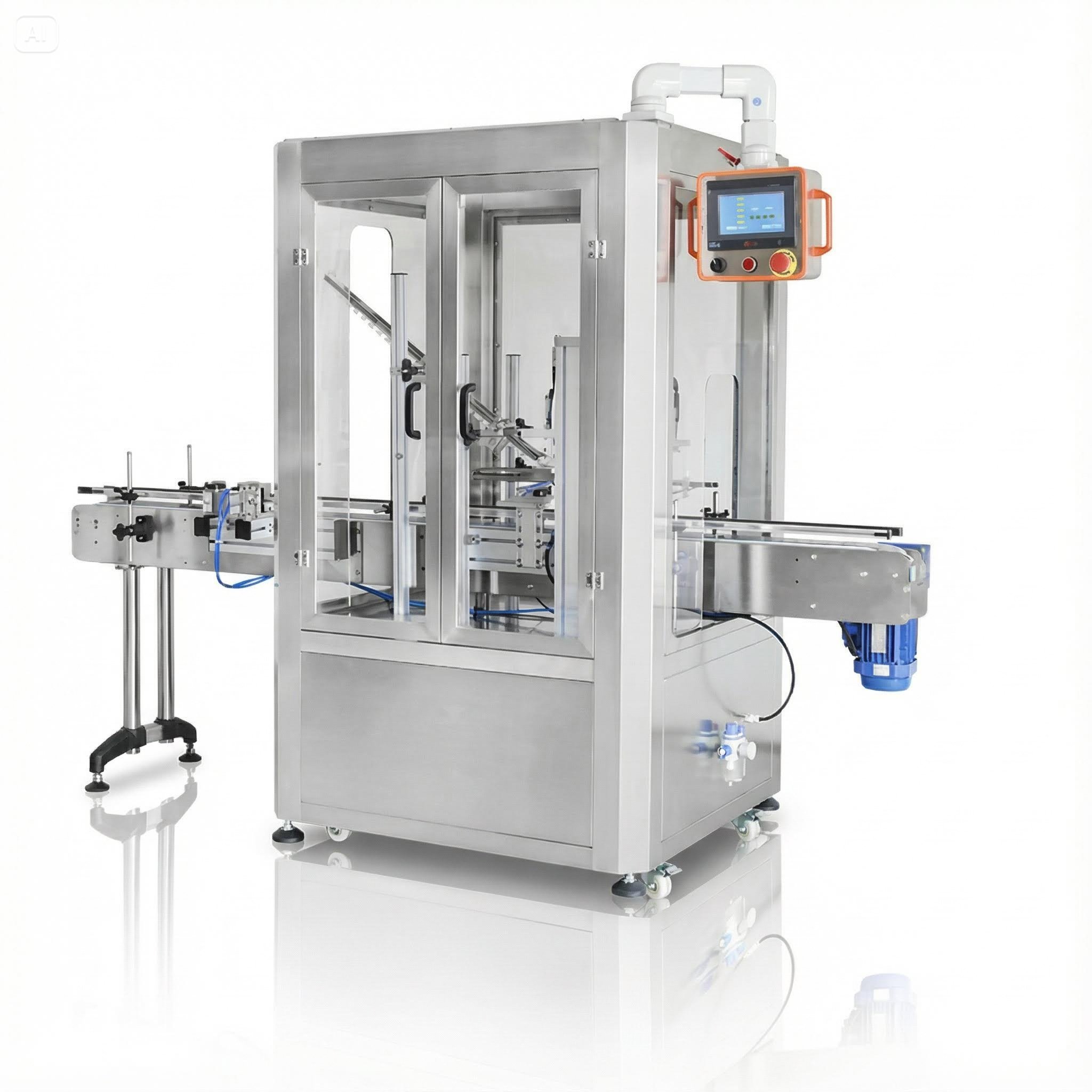
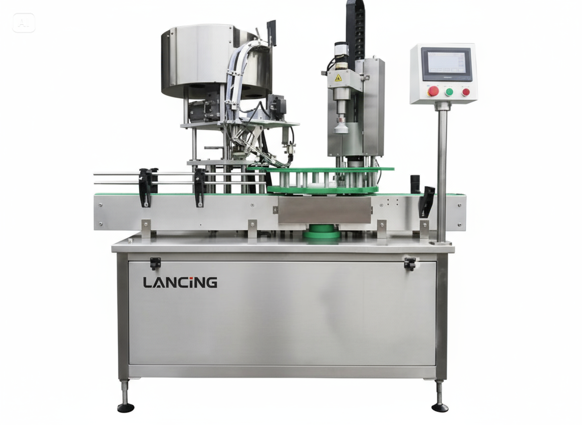
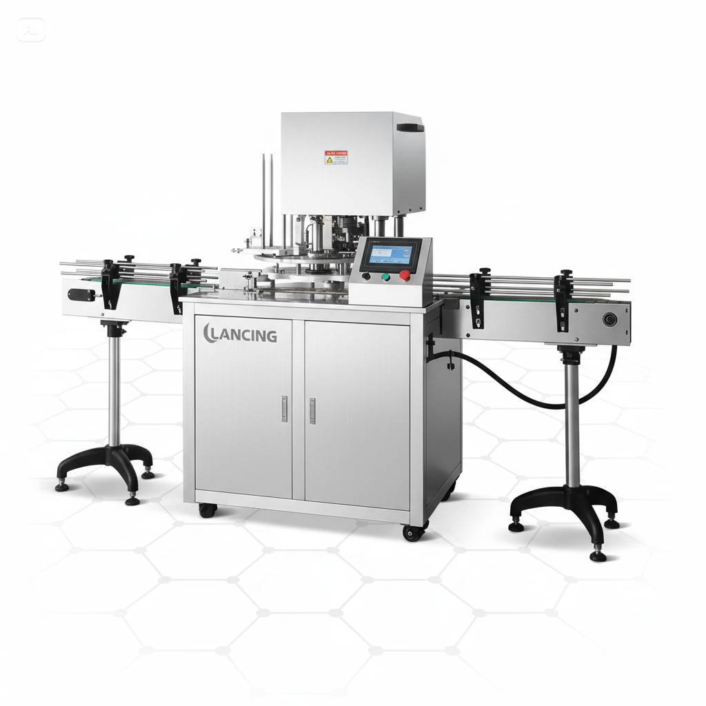
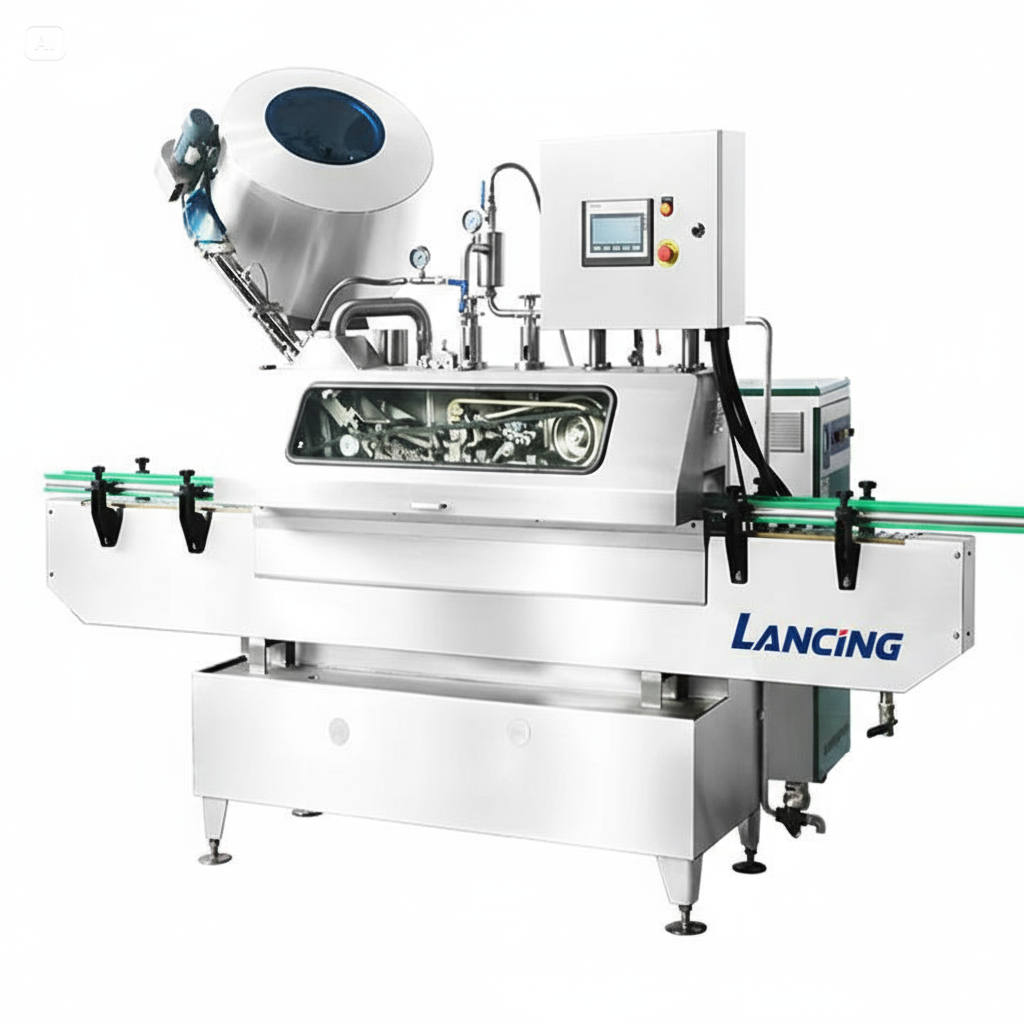
Capping machine selection guide
Choose the application and feeding method around the complete closure system.

Capping machinery guidance
Capping performance depends on the closure, neck finish, container stability and the way caps are presented. The correct starting point is the physical closure rather than the broad product industry.
Check cap diameter, thread engagement, closure height, torque requirement and whether a dip tube or trigger makes the closure difficult to handle. Compare screw capping and pump capping.
ROPP, crimp and crown closures use different tooling and require accurate container support. See ROPP, crimp and crown capping.
T-corks, vacuum caps and triggers have distinct feeding and application needs. Review T-cork, vacuum and trigger capping.
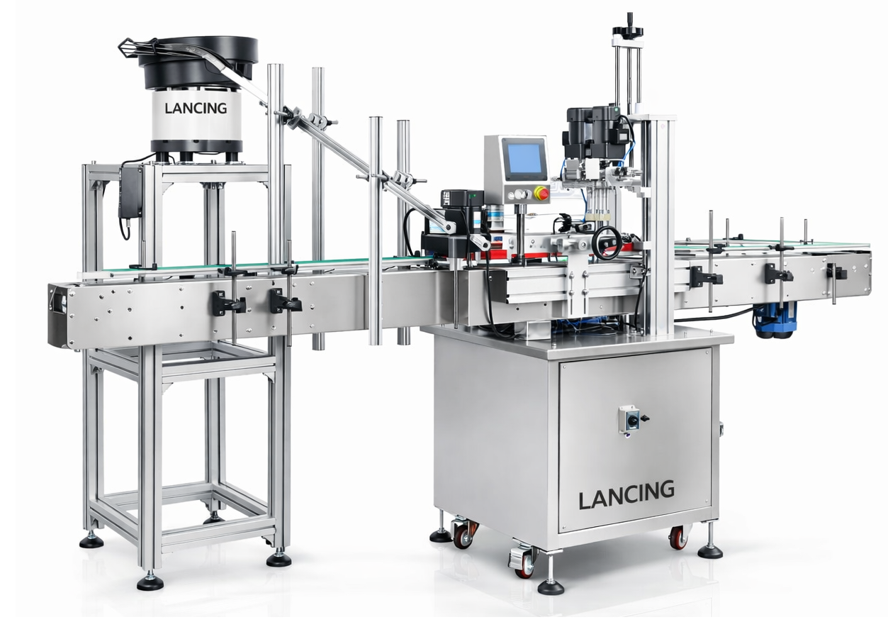
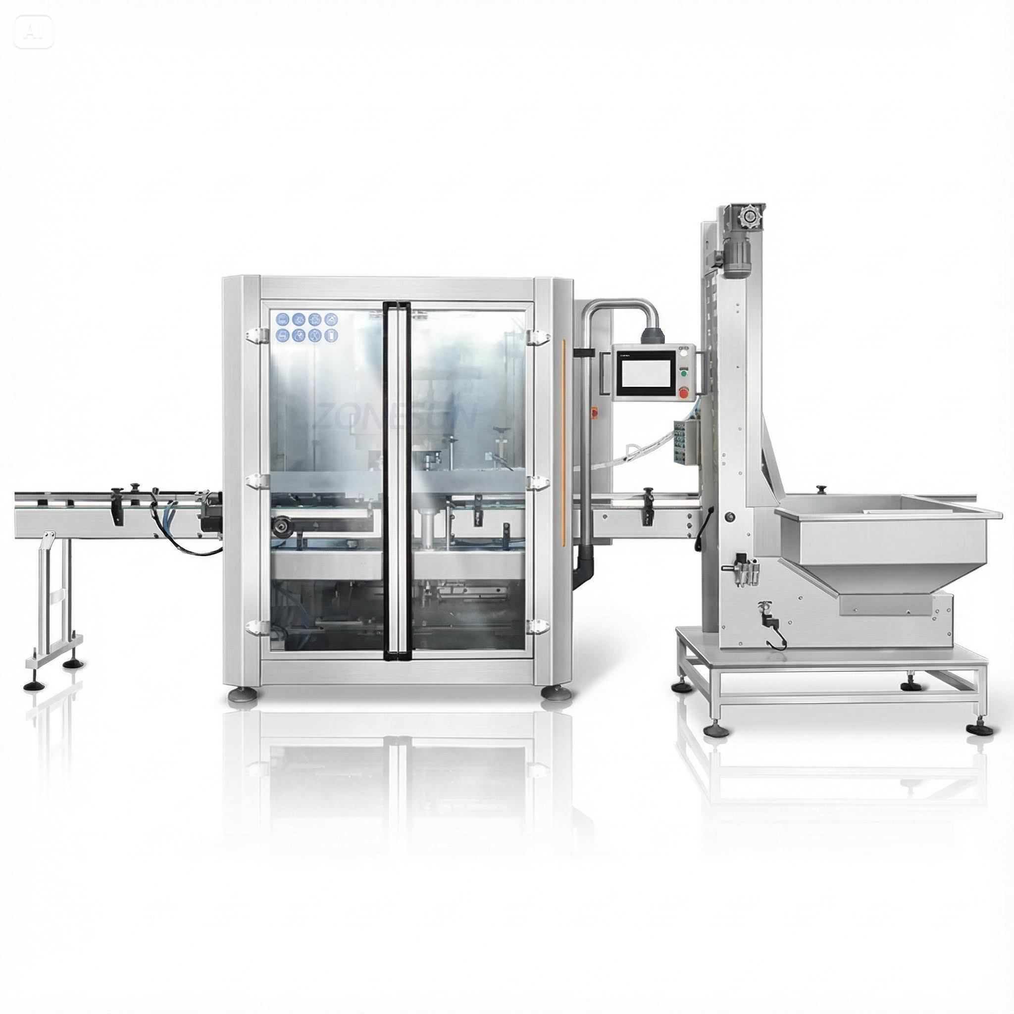
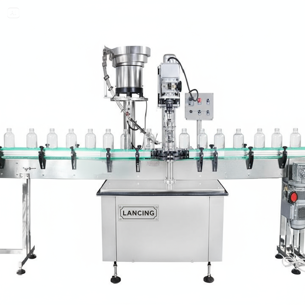
A capper may apply a manually placed closure or receive caps from a bowl, elevator or other feeder. Automatic feeding is only practical when the closure can be orientated consistently and transferred without tangling or damage. Pumps, triggers and closures with long dip tubes often need particular handling.
Torque must be sufficient to secure the closure without deforming the cap, damaging the thread or making the pack difficult to open. Bottle support, chuck or spindle contact, cap finish and product contamination around the neck can all affect the result. Samples of the production closure and container are therefore essential.
Send matched container and closure samples for a practical capping review.
Discuss a capping applicationMany machines can be adjusted or fitted with change parts, but the practical range depends on closure geometry and container handling. Every cap and bottle combination should be listed.
No. Short runs can suit manual cap placement, while higher-output lines may justify an automatic feeder. The closure must be tested for reliable orientation and transfer.
Use the agreed closure and bottle with a defined torque or functional acceptance method. Actual results depend on threads, materials, liner, product around the neck and application tooling.
They can be, but dip tubes and irregular closure shapes make feeding and placement more demanding than a simple screw cap. Samples are needed to select the handling method.
Provide the filler discharge height, conveyor dimensions, bottle spacing and control interface so the capper can be integrated without unstable transfers or repeated stoppages.
Closure application resources
The closure system—not cap diameter alone—determines capping technology, container support, automatic presentation and the test needed to confirm the finished pack.
Use production-quality caps and containers to define thread or engagement, liner, tamper feature, dip tube, decoration, orientation and tolerance. The capping machine guide covers screw, ROPP, crown, T-cork, pump, trigger, crimp, press and vacuum closure considerations.
State whether the result is checked by applied or removal torque, thread formation, crimp profile, insertion height, leak test, visual orientation or another method. Record instrument, timing and sample method.
Choose the application and feeding method around the complete closure system.
Prepare sample quantities, test sequence and repeatable acceptance checks.
Coordinate filled-container transfer, capper timing and stable discharge to labelling.
Ready to discuss the application?
Send the application details to Lancing for a tailored machinery review.
Capping selection questions
A capping system must present the closure, stabilise the container and apply the required result without damaging either component. These questions help separate feeding, handling and tightening problems before a machine is selected.
Cross-threading usually begins when the cap is not square to the neck as the thread engages. Causes can include poor cap presentation, bottle lean, neck or cap variation, unstable transfer, excessive initial pressure, damaged threads or timing that allows the closure to enter at an angle.
Inspect the cap before tightening, not only after failure. Record whether the problem follows a particular closure batch, container cavity, speed or guide setting. The correction may belong in feeding, placement or bottle support rather than the final torque stage.
The cap torque troubleshooting guide provides an evidence sequence.
The container must resist the vertical and rotational forces created during closure application. Flexible or unstable packs may need side belts, neck support, base support or a fixture so the capper can apply a repeatable action without distorting or spinning the bottle.
Test filled containers where product mass changes stability. Include the lightest, tallest and least rigid format, and check label or decoration areas that must not be marked by guides. Bottle support is part of capping performance, not a separate cosmetic detail.
For complete-line handling, use the integration guide.
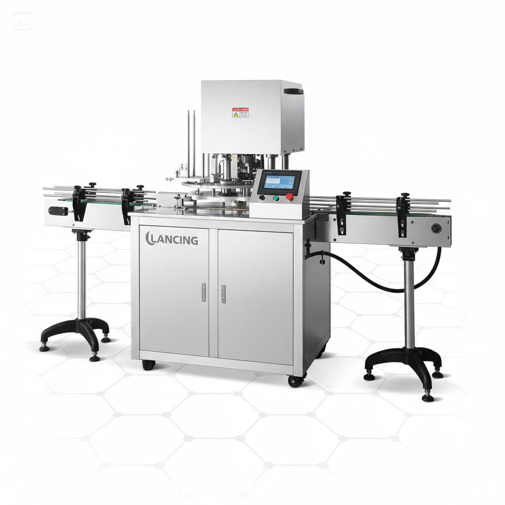
A chuck capper is often considered when the closure can be captured by dedicated tooling for a controlled tightening cycle, while a spindle capper is often considered for continuous inline handling with opposed rotating wheels. The application, closure geometry and required changeover determine the better route.
Neither method guarantees a torque result by name alone. Compare cap presentation, tooling contact, container support, closure variation, throughput duty and the way applied or removal torque will be checked.
Read the detailed spindle versus chuck capping comparison.
Provide production closures and matching containers from representative batches, including known difficult examples. A few perfect samples can prove basic geometry but cannot demonstrate the variation a feeder and capper will see in routine production.
Include liners, pumps, triggers, overcaps or inserts exactly as supplied to production. State the neck finish, application sequence, target result, acceptable cosmetic contact and the method used to check the closure after application.
Use the sample-trial guide to label and document the set.
Send matched containers and closures, neck information, target application result and representative variation so feeding and tightening can be reviewed together.
Discuss the applicationCapping project specification
A capper cannot be selected from closure diameter alone. The closure and neck finish, liner or tamper feature, orientation, supply condition, container stability and accepted finished result all affect the machine principle and tooling.
Prepare closure, neck, feeding, torque and sample information.
Define restraint, orientation, tolerances and the filled-pack condition.
Compare two relevant screw-closure application principles.
Where pumps, triggers, droppers or long dip tubes are involved, include complete assembled components and define the required facing direction. Acceptance should be based on the verified pack result—such as engagement, seal or controlled torque test—not on an unsupported machine setting.
© Copyright 2025 by Lancing Ltd - all right reserved terms & conditions